 |
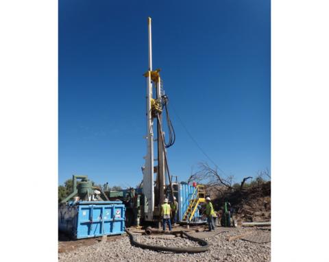
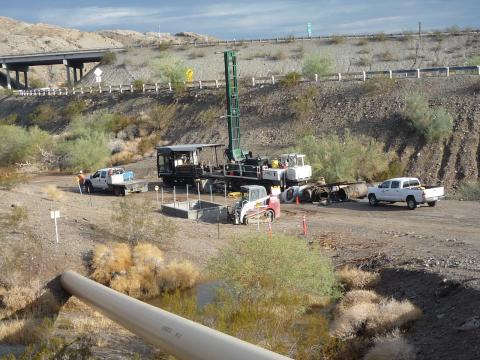
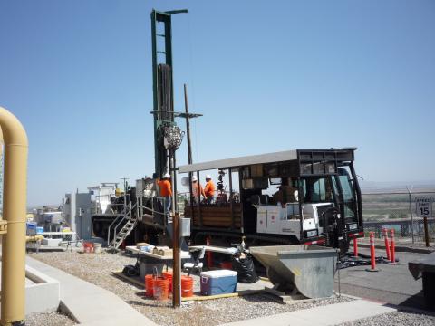
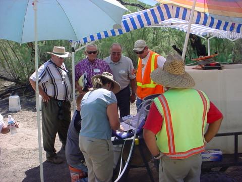
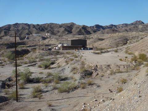
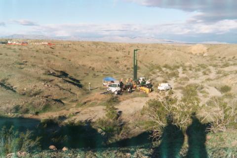
Drilling a freshwater well at the Site "B" fresh water investigation site in Arizona. |
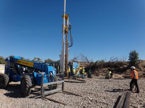 |
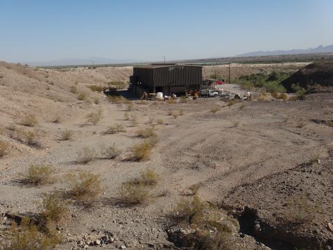
Drilling a freshwater well at the Site "B" fresh water investigation site in Arizona. |
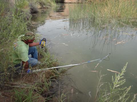 |
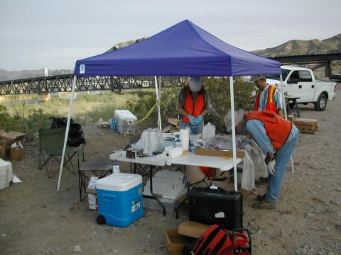
Topock Compressor Station (IM-3) employee, collecting water quality data from the bank of the Colorado River with Red Rock bridge in the background. |
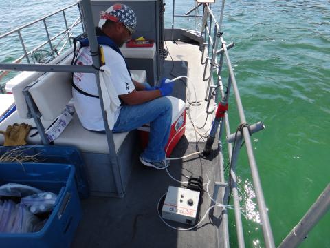 |
Topock Compressor Station (IM-3) employee, taking surface water samples from a boat on the Colorado river with a peristaltic pump in foreground. |
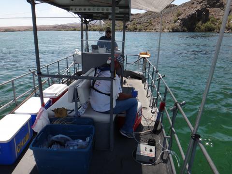 |
Topock Compressor Station (IM-3) employee, taking surface water samples from the Colorado River with sample coolers on the left and Captain Doyle operating the boat at the stern. |
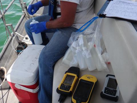 |
Close-up of Topock Compressor Station (IM-3) employee, taking a surface water samples from a boat on the Colorado River with empty sample bottles, GPS, and water quality instrumentation in the foreground. |
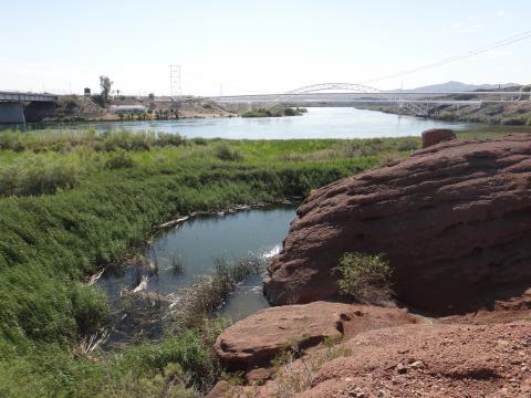 |
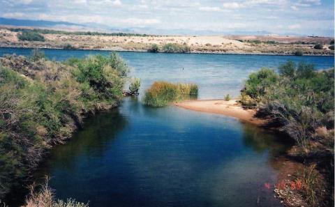
View of the wetlands (surface water sampling locations SW-1 and SW-2) toward the PG&E arch bridge, looking southeast |
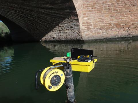 |
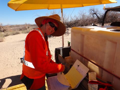
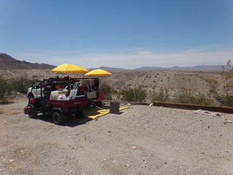
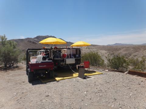
Data is being downloaded from the Red Rock Bridge transducer (a surface water monitoring location). This monitoring location is at Red Rock bridge under the national trails highway and at the mouth of Bat Cave Wash. |
 |
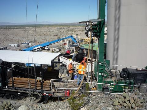
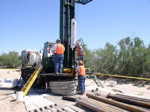
Drilling of the borehole for the future monitoring well MW-71-35 |
 |
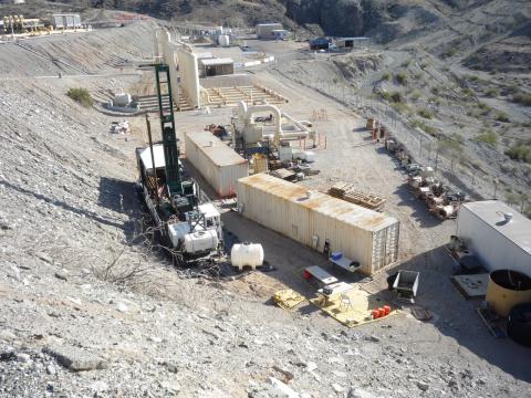
Drilling of the borehole for the future monitoring well MW-74-240 |
 |
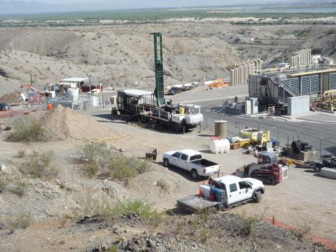
Drilling of the borehole for the future monitoring well cluster, MW-66 |
 |
Drilling of the borehole for the future monitoring well MW-69-195 |
 |
Drilling of the borehole for the future monitoring well cluster, MW-67 |
 |
Sampling MW-66BR-270 at the Topock Compressor Station (looking Northwest) |
 |
Sampling MW-66BR-270 at the Topock Compressor Station (looking Northeast) |
 |
View from river sampling location (RRB), or mouth of Bat Cave Wash at the Red Rock Bridge, looking towards the Colorado River, circa April 2003 |
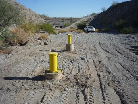 |
Repairs to monitoring wells MW-38S, MW 38D and Old Well/Pipe Reconnaissance in 2013. The post‐repair photograph is prior to tire track removal and painting of the wellhead casing. |
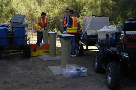 |
Groundwater sampling at Monitoring well MW-43 cluster in October 2006 |
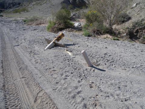 |
Pre‐repair photograph of MW‐38S and MW‐38D, circa February 2013 |
 |
Groundwater sampling at the MW-33 cluster on the floodplain |
 |
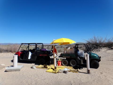
Field worker on the floodplain setting up for groundwater sampling |
 |
Groundwater sampling near Topock Compressor Station (at TW-01, looking southwest). |
 |
Groundwater sampling near Topock Compressor Station (at TW-01, looking south). |
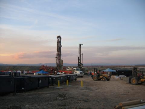 |
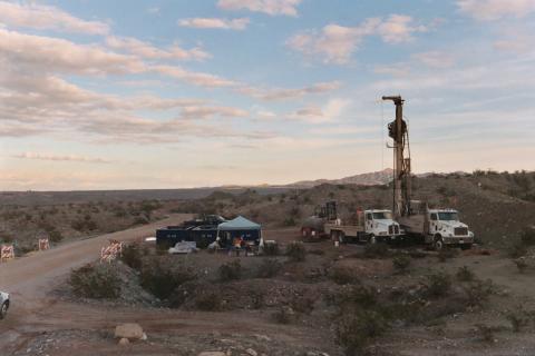
Drilling rigs on the East Mesa |
 |
Additional "pot-holing" activities from a different view point |
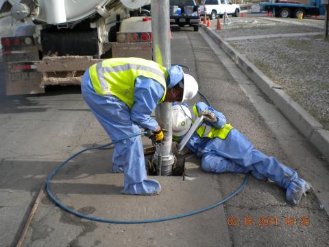 |
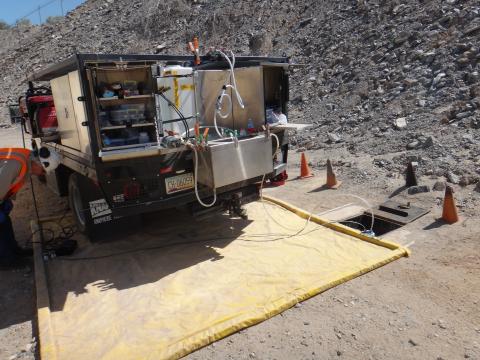
Additional "pot-holing" activities to safely locate buried utilities within the Topock Compressor Station |
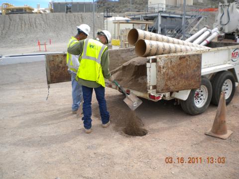 |
Filling in the "pot-hole" |
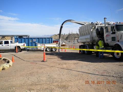 |
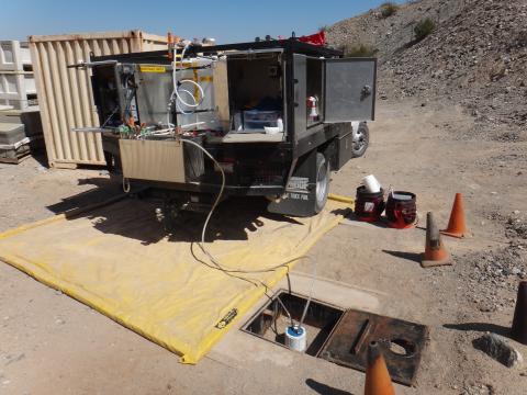
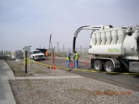
Use of a Vacuum Truck to "pot-hole" to safely locate buried utilities within the Topock Compressor Station |
 |
Sampling wells on the floodplain and discussing field parameters with Tribes, June 2004 |
 |
Sampling at MW-39 cluster on the floodplain in January of 2005, close-up view |
 |
Sampling at MW-39 cluster on the floodplain in January of 2005, prior to neutral paint color of the outside of the wells |
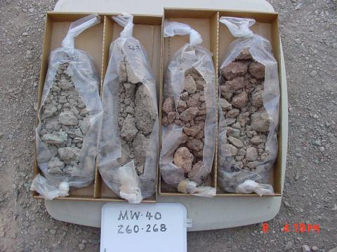 |
Soil core samples from monitoring well MW-40, the well in the median of Interstate 40, circa May 2004 |
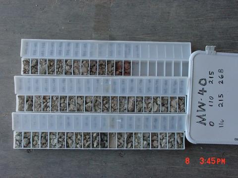 |
Cataloging core samples from the drilling of monitor well MW-40 |
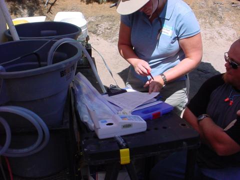 |
Recording water quality data during groundwater sampling at MW-34-80 |
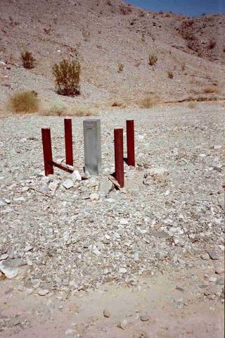 |
Monitoring Well in Bat Cave Wash prior to neutral painting |
 |
View of the IM-3 treatment plant looking south |
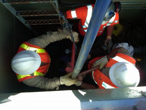 |
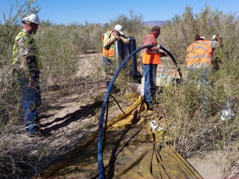
Workers connect drop pipe during installation of new pump at extraction well PE-01, March 2012. |
 |
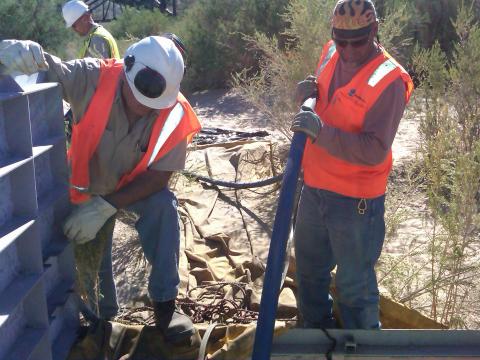
Installation of the new pump at PE-1, March 2012 |
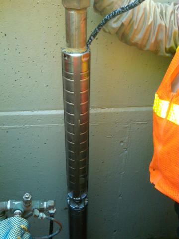 |
Work done to Replace the pump at extraction well PE-1, March 2012. Photograph of new pump prior to installation |
 |
Work done to Replace the pump at extraction well PE-1, March 2012 |
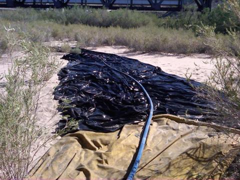 |
Work done to Replace the pump at extraction well PE-1, March 2012. |
 |
Current Topock Site photograph looking south/southeast towards IM-3 Treatment Plant (2013) |
 |
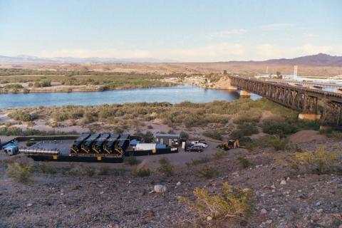
View of the MW-20 bench during IM-2 groundwater extraction activities, May 2004 |
 |
Current Topock Site photograph looking north towards IM-3 Treatment Plant (2013) |
 |
IM-1: Installation of MW-36 floodplain wells, April 2004 |
 |
Logging core samples from IM-1 well drilling |
 |
IM-1: Installation of floodplain monitoring wells, March - May 2004 |
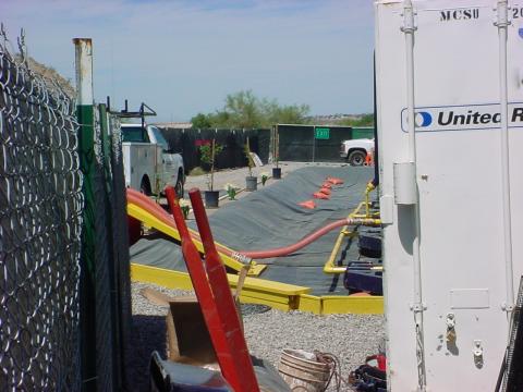 |
IM-2: Protective berms and ground liners at the MW-20 bench |
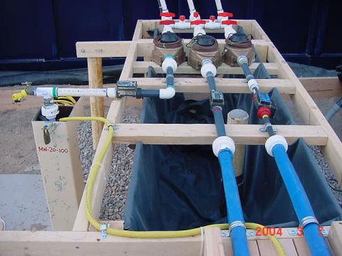 |
MW-20-100 monitoring well with old extraction and containment system, 2004 |
 |
View of the MW-20 bench during IM-2 groundwater extraction activities, January 2005 |
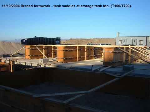 |
Braced framework of the Storage Tank foundation, November 2004 |
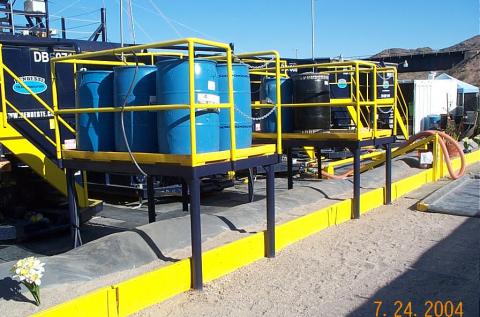 |
IM-3 batch treatment chemical containers at the MW-20 bench in 2004. |
 |
Groundwater extraction from the MW-20 monitoring wells, March 2004 |
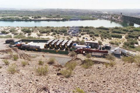 |
IM-2 water transport trucks arrive and depart from MW-20 bench, circa 2004-2005 |
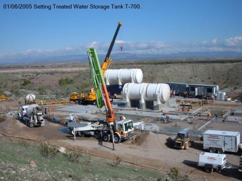 |
Setting T-700 (treated water storage tank) at the IM-3 treatment plant, January 2005 |
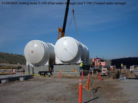 |
Setting tanks T-100 (raw water storage) and T-700 (treated water storage) at the IM-3 treatment plant, January 2005 |
 |
View of the IM-3 Treatment Facility from the Topock Compressor Station |
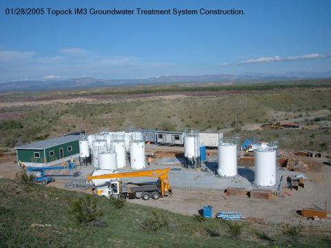 |
Construction of the Topock IM-3 Treatment Plant, January 28, 2005 |
 |
View from South toward the IM-3 Treatment Facility, February 2006 |
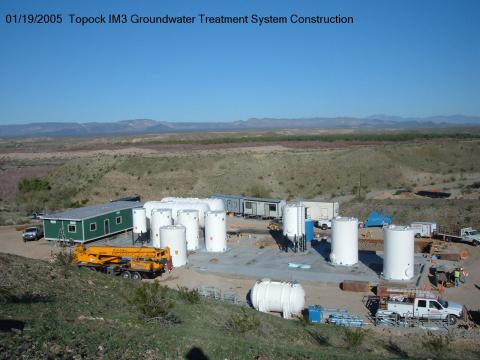 |
Construction of the Topock IM-3 Treatment Plant, January 19, 2005 |
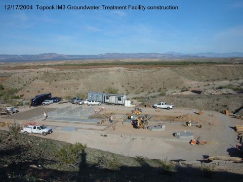 |
Construction of the Topock IM-3 Treatment Plant, December 17, 2004 |
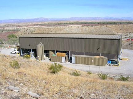 |
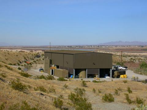
IM-3 Treatment Facility after construction activities are completed, circa 2006 |
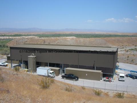 |
Construction of the Topock IM-3 Treatment Plant, July 2005 |
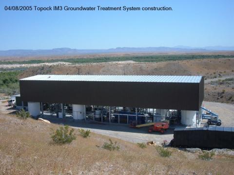 |
Construction of the Topock IM-3 Treatment Plant, April 2005 |
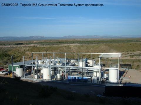 |
Construction of the Topock IM-3 Treatment Plant, March 9, 2005 |
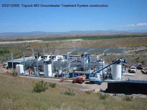 |
Construction of the Topock IM-3 Treatment Plant, March 21, 2005 |
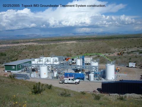 |
Construction of the Topock IM-3 Treatment Plant, February 2005 |
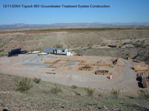 |
Construction of the Topock IM-3 Treatment Plant, December 11, 2004 |
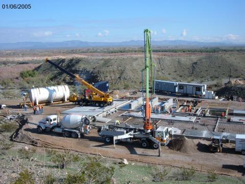 |
Construction of the IM-3 Treatment Plan, January 2005 |
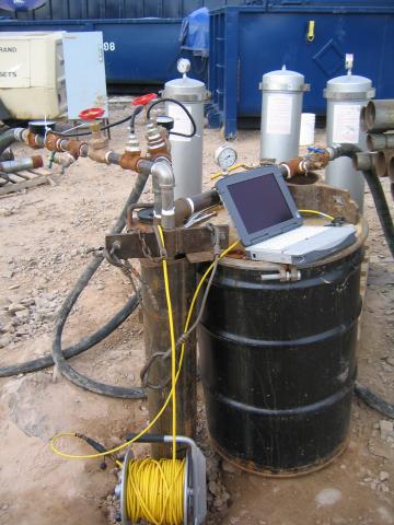 |
Water level monitoring during testing at injection well #3, date unknown |
 |
Preparing to install injection well #3 casing |
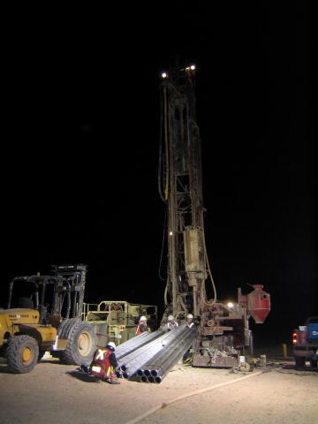 |
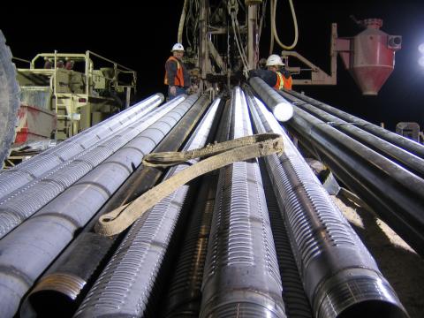
Drilling of injection well #3 at night |
 |
Compliance well installation in the injection well field |
 |
Drilling a Compliance well. |
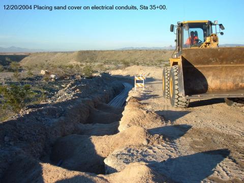 |
Placing Sand Cover on Electrical Conduits, December 2004 |
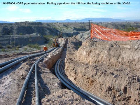 |
HDPE Pipe Installation: Laying the pipe after fusing sections together |
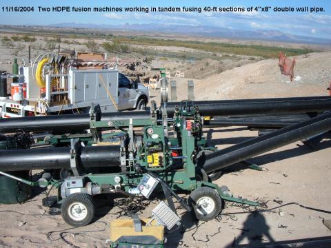 |
Two HDPE fusion machines working in tandem fusing 40-ft sections of 4'x8' double wall pipe, November 2004 |